Metalluragical Microscope
BX53

Contact
BX53
Olympus
Contact

Available on backorder

Catalogue

Designed for Industrial and Materials Science Applications

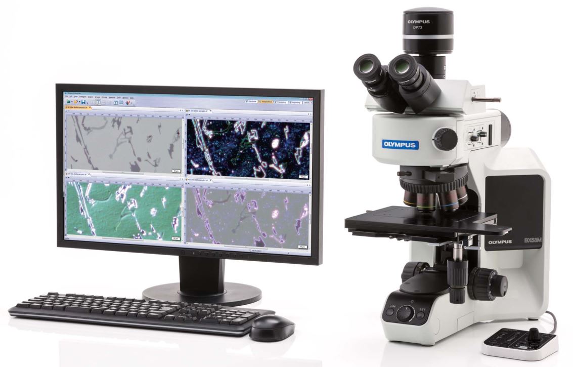
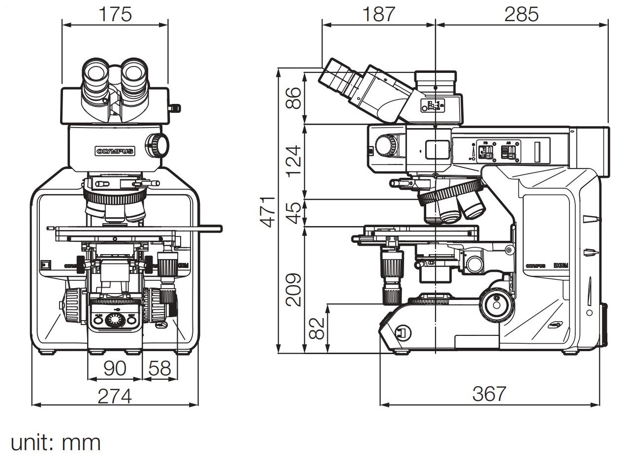
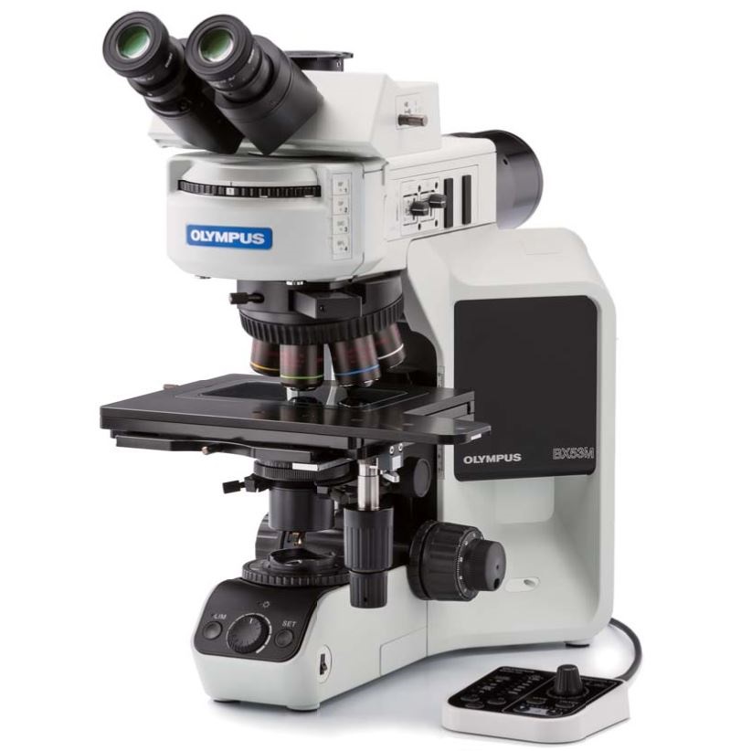
Designed with modularity in mind, the BX3M series provide versatility for a wide variety of materials science and industrial applications. With improved integration with OLYMPUS Stream software, the BX3M provides a seamless workfl ow for standard microscopy and digital imaging users from observation to report creation.

Simple Illuminator: Traditional techniques made easy

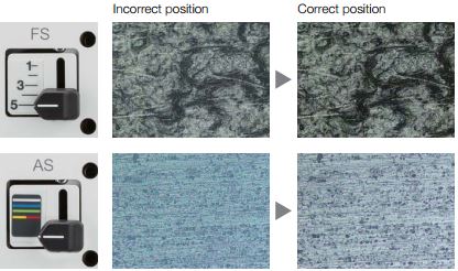
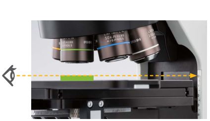
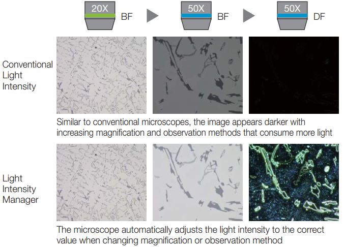
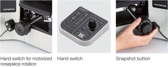
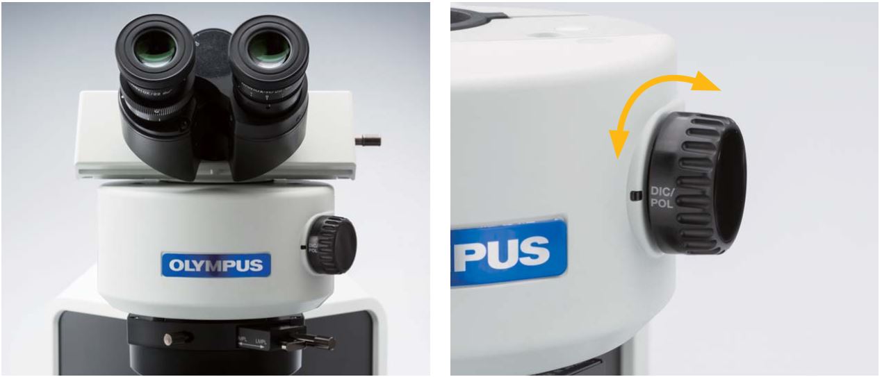
The illuminator minimizes complicated actions that are usually necessary during microscope operation. A dial at the front of the illuminator enables the user to easily change the observation method. An operator can quickly switch between the most frequently used observation methods in reflected light microscopy, such as from brightfield, to darkfield, to polarized light, in order to readily change between different types of analyses. In addition, simple polarized light observation is adjustable by rotating the analyzer.

Intuitive Microscope Controls

Using the proper aperture stop and field stop settings provides good image contrast and makes full use of the numerical aperture of the objective. The legend guides the user to the correct setting based on the observation method and objective in use

Focus Scale Index: Find the focus quickly

The focus scale index on the frame supports quick access to the focal point. Operators can roughly adjust the focal point without viewing the sample through an eyepiece, saving time when inspecting samples that are different heights.


Coded Hardware: Easily restore microscope settings

The BX3M employs new coded functions that integrate the microscope’s hardware settings with OLYMPUS Stream image analysis software. The observation method, illumination intensity, and objective position are all recorded within the software and/or the handset. The coded functions enable the microscope settings to be automatically saved with each image, making it easier to reproduce the settings at a later time and provide documentation for reporting purposes. This saves the operator time and minimizes the chance that an incorrect setting will be used. The current observation settings are always clearly displayed both on the hand switch and in the software.

Light Intensity Manager: Consistent illumination

During the initial setup, the illumination intensity can be adjusted to match the specific hardware configuration of the coded illuminator and/or coded nosepiece.

Easy and Ergonomic Operation

Ergonomics are of the utmost importance for all users. Both standalone microscope users and those integrating with OLYMPUS Stream image analysis software benefit from ergonomic handset controls that clearly display the hardware position. The simple handsets enable the user to focus on their sample and the inspection they need to perform.


Applications

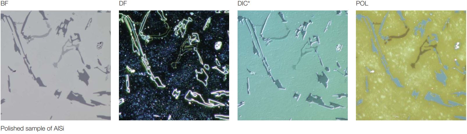
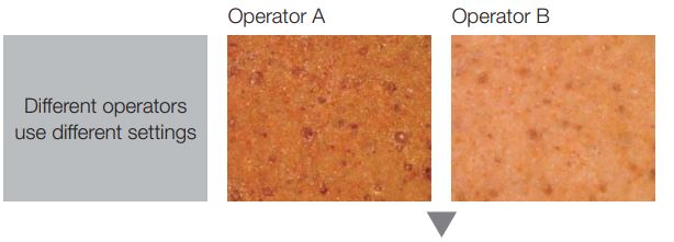
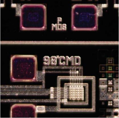
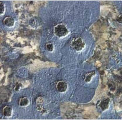
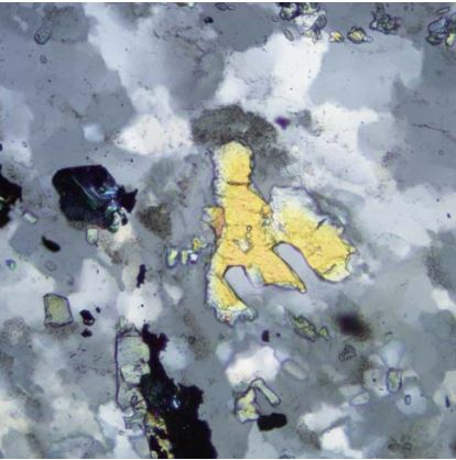
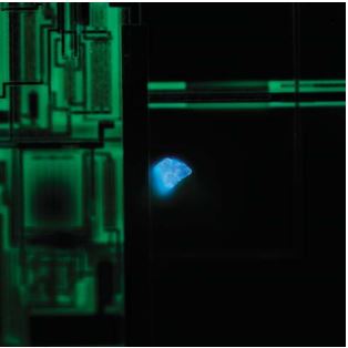
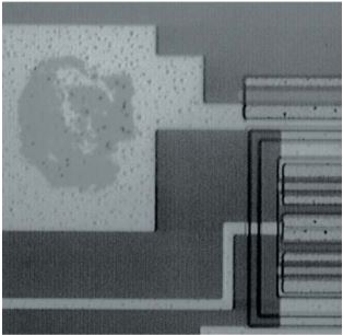
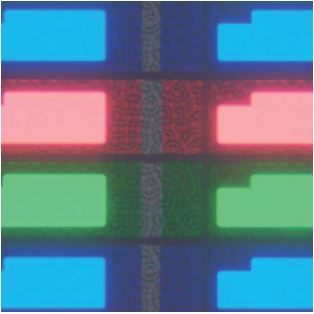
Reflected light microscopy spans a range of applications and industries. These are just a selection of examples of what can be achieved using different observation method

DarkfieldSurface mounting board: DF

Darkfield enables the observation of scattered or diffracted light from the specimen. Anything that is not flat reflects this light while anything that is flat appears dark so imperfections clearly stand out. The user can identify the existence of even a minute scratch or flaw down to the 8 nm level—smaller than the resolving power limit of an optical microscope. Darkfield is ideal for detecting minute scratches or flaws on a specimen and examining mirror surface specimens, including wafers.

Differential Interference ContrastNodular cast iron etched: DIC

DIC is a microscopic observation technique in which the height difference of a specimen not detectable with brightfield becomes a relief-like or threedimensional image with improved contrast. This technique utilizes polarized light and can be customized with a choice of three specially designed prisms. It is ideal for examining specimens with very minute height differences, including metallurgical structures, minerals, magnetic heads, hard-dis media, and polished wafer surfaces

Polarized LightSericite: POL

This microscopic observation technique utilizes polarized light generated by a set of filters (analyzerand polarizer). The characteristics of the sample directly affect the intensity of the light reflected through the system. It is suitable for metallurgical structures (i.e., growth pattern of graphite on nodular casting iron), minerals, LCDs and, semiconductor materials.


FluorescenceParticle on semiconductor wafer: FL

This technique is used for specimens that fluoresce (emit light of a different wavelength) when illuminated with a specially designed filter cube that can be selected to the specific application. It is suitable for inspection of contamination on semiconductor wafers, photo-resist residues, and detection of cracks through the use of fluorescent dye. An optional apochromatic lamp housing collector lens system can be added to compensate for chromatic aberrations from visible light to near-infrared light.


Infra-RedElectrode section: IR

IR observation is the preferred method of nondestructively inspecting the inside of electronic devices constructed with silicon or glass that easily transmit IR wavelengths of light.


Transmitted Light ObservationLCD color fi lter: TL BF + HDR

For transparent samples such as LCDs, plastics, and glass materials, true transmitted light observation is available by using a variety of condensers. Examining samples in transmitted brightfield and polarized light can be accomplished all in one convenient system.


Specifications


BX53MTRF-S

BX53MRF-S

BXFM

Optical system

UIS2 optical system (infinity-corrected)

Microscope frame

Illumination

Reflected/transmitted

Reflected

Focus

Stroke: 25 mm 

Stroke: 30 mm 

Fine stroke per rotation: 100 μm 

Fine stroke per rotation: 200 μm 

Minimum graduation: 1 μm 

Minimum graduation: 2 μm 

With upper limit stopper, torque adjustment for coarse handle

With torque adjustment for coarse handle

Max. specimen height

35 mm (w/o spacer) 

65 mm (w/o spacer) 

Depends on the mounting configuration

75 mm (with BX3M-ARMAD)

105 mm (with BX3M-ARMAD)

Observation tube

Wide-field FN 22

Inverted: binocular, trinocular, tilting binocular 

Erect: trinocular, tilting binocular

Super-wide-field FN 26.5

Inverted: trinocular 

Erect: trinocular, tilting trinocular

Reflected light illumination

Traditional observation technique

BX3M-RLAS-S 

Coded, white LED, BF/DF/DIC/POL/MIX FS, AS (with centering mechanism) 

BX3M-KMA-S 

White LED, BF/DIC/POL/MIX FS, AS (with centering mechanism) 

BX3M-RLA-S 

100W halogen lamp, white LED, BF/DF/DIC/POL/MIX/ FS, AS (with centering mechanism), 

BF/DF interlocking, ND filter

U-KMAS 

White LED, 100W halogen 

Fiber illumination, BF/DIC/POL/MIX

Fluorescence

BX3M-URAS-S 

Coded, 100W mercury lamp, 4 position mirror unit turret, (standard: WB, WG, WU+BF etc) 

With FS, AS (with centering mechanism), with shutter mechanism

Transmitted light

White LED 

Abbe/long working distance condensers

Revolving nosepiece

For BF

Sextuple, centering sextuple, septuple, coded quintuple (optional motorized revolving nosepieces)

For BF/DF

Sextuple, quintuple, centering quintuple, coded quintuple (optional motorized revolving nosepieces)

Stage

Coaxial left (right) handle stage: 

76 mm × 52 mm, with torque adjustment 

Large-size coaxial left (right) handle stage: 

105 mm × 100 mm, with locking mechanism in Y-axis 

Large-size coaxial right handle stage: 

150 mm × 100 mm, with torque adjustment and locking mechanism in Y-axis

Weight

Approx. 18.3 kg 

Approx. 15.8 kg 

Approx. 11.1 kg 

(Microscope frame 7.6 kg)

(Microscope frame 7.4 kg)

(Microscope frame 1.9 kg)


Dimensions