Open time: 8 : 00 AM - 5 : 30 PM (Monday - Saturday)
Open time: 8 : 00 AM - 5 : 30 PM (Monday - Saturday)
Available on back-order
7.5 Color TFT LCD
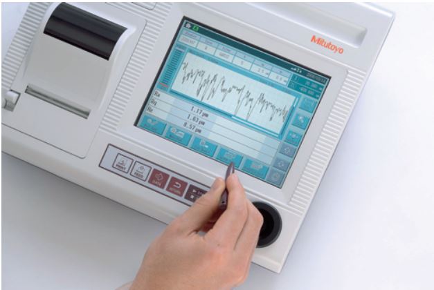
The dedicated data processor has a high-visibility 7.5″ color TFT LCD. Icon display and touch panel operation provide user-friendly display and easy operation.
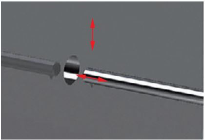
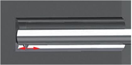
Positioning by joystick and manual control knobs on the processor
Easy-to-operate joystick. Fine positioning of stylus required for small-hole measurements can be easily performed using the manual fine-adjustment knobs.
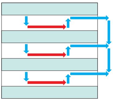
Multiple trace function
A machine can be programmed to take up to three traces, one after the other.
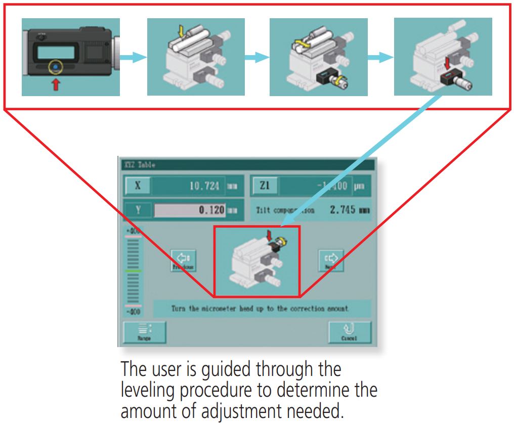
Auto leveling table (optional)
Automatically levels the surface to be tested for easy, strain-free setup.
Capable of fine-contour analysis
Supports 43 types of analysis parameters, complying with surface roughness standards such as ISO 1997 and JIS 2001. Also capable of various fine-contour analysis.
* Contour analyses: Area, circle, angle, coordinate difference, step, inclination
Ceramic guideway
A ceramic guideway, inherently free from wear and deterioration with age, is employed to maintain the traversing straightness of the drive unit (X-axis) indefinitely. Maintenance-free design, ince anti-corrosion treatment is not required for ceramic.
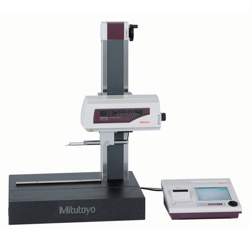
A high-visibility 7.5″ color TFT LCD, color icon display and touchoperated panel provide user-friendly, easy operation. Built-in thermal printer. Fine contour analysis provided as standard.
Supports 16 languages
Japanese, English, German, French, Italian, Spanish, Portuguese, Korean, Simplified Chinese, Traditional Chinese, Czech, Polish, Hungarian, Turkish, Swedish, Dutch
SV-2100S4/H4/W4
X-axis tracing with programmed Z-axis shifts possible
Both a fast-traverse joystick (X-axis: .78″/s (20mm/s) for SJ-500, 1.98″/s (40mm/s) for SV-2100, Z2-axis: .78″/s (20mm/s) for SV2100S4/H4/W4) and manual fine-adjustment knobs, essential or positioning in small hole measurement, are standard features.
When using an optional 3-axis adjustment table or leveling table, a navigation screen is available to help the operator level the surface to be tested.
|
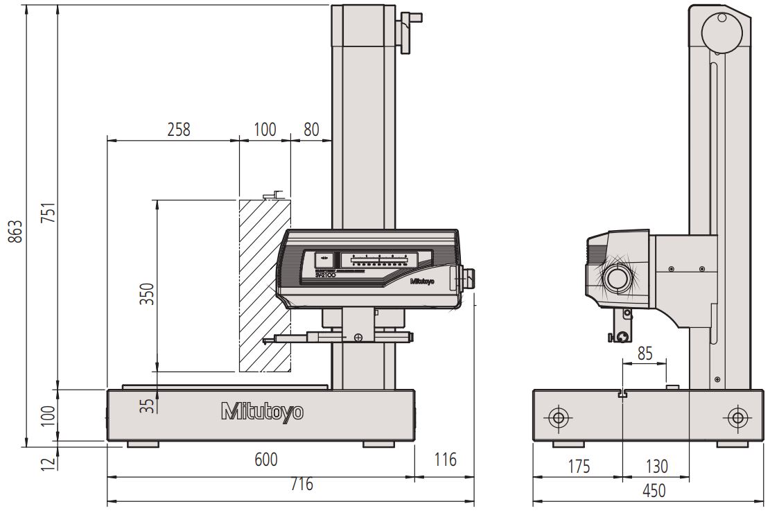
Traverse:
|
100 mm
|
|
Measuring speed:
|
0.02 – 5 mm/s
|
|
Drive speed:
|
X = 0-40 mm/s
Z2 = 0-20 mm/s or joystick operation |
|
Traverse straightness:
|
0,15 µm / 100 mm
|
|
Measuring method:
|
Skidless – Differential inductance
|
|
Range:
|
800 µm; 80 µm; 8 µm
(up to 2,4 mm with an optional stylus) |
|
Profiles:
|
Primary Profile (P), Roughness Profile (R), Waviness (W), MOTIF (R, W) and more
|
|
Standard:
|
EN ISO, VDA, JIS, ANSI and customize settings
|
|
Analysis graphs:
|
BAC, ADC
|
|
Digital filter:
|
Gauss, 2CR75, PC75, RobustSpline
|
|
Cut-off length:
|
λc : 0.025 mm; 0.08 mm; 0.25 mm; 0.8 mm; 2.5 mm; 8 mm; 25 mm;
80 mm λs : 0.25 µm; 0.8 µm; 2.5 µm; 8 µm; 25 µm; 80 µm; 250 µm; none λf : 0.08 mm; 0.25 mm; 0.8 mm; 2.5 mm; 8 mm; 25 mm; 80 mm; none |
|
Printer:
|
Built-in thermal type
|
|
Display:
|
7.5″ colour TFT with backlight
|
|
Power supply report:
|
UN 38.3 Test Summary Report
|