Open time: 8 : 00 AM - 5 : 30 PM (Monday - Saturday)
Open time: 8 : 00 AM - 5 : 30 PM (Monday - Saturday)
Available on back-order
| Projected image | Inverted image | |
| Protractor screen | Effective diameter | 12.4” / 315mm |
| Screen material | Fine ground glass | |
| Reference line | Cross hair line | |
| Angle display (LED) | Resolution: 1° or 0.01° (switchable), Range: ±360° Functions: Absolute/incremental mode switching, Zero Set |
|
| Projection lens | Standard Accessory 10X (172-202 | |
| Magnification accuracy | Contour illumination | ±0.1% or les |
| Surface illumination | ±0.15% or less | |
| Contour illumination | Light source | Halogen bulb (24V, 150W) |
| Optical system | Telecentric system | |
| Functions | Telecentric system | |
| Surface illumination | Light source | Halogen bulb (24V, 150W |
| Optical system | Vertical illumination with a half-reflection mirror | |
| XY range | 6” x 2” (150 x 50mm) | |
| Resolution | .0001”/0.001mm | |
| Measuring Unit | Built-in linear scales | |
| Table size | 11.02×5.98”(280x152mm) | |
| Effective table area | 7.24×3.23”(184x82mm) | |
| Max. workpiece height | 4.07” (103.5mm) | |
| Functions | Zero-setting, ± directionswitching, SPC output | |
| Power supply | 120V AC, 50/60Hz | |
| Mass | 255 lbs. (116kg) | |
| Standard accessories | 10X projection lens set, masking shield, power cord, halogen bulb, fuse, grounding wire, allen wrench, vinyl cove | |
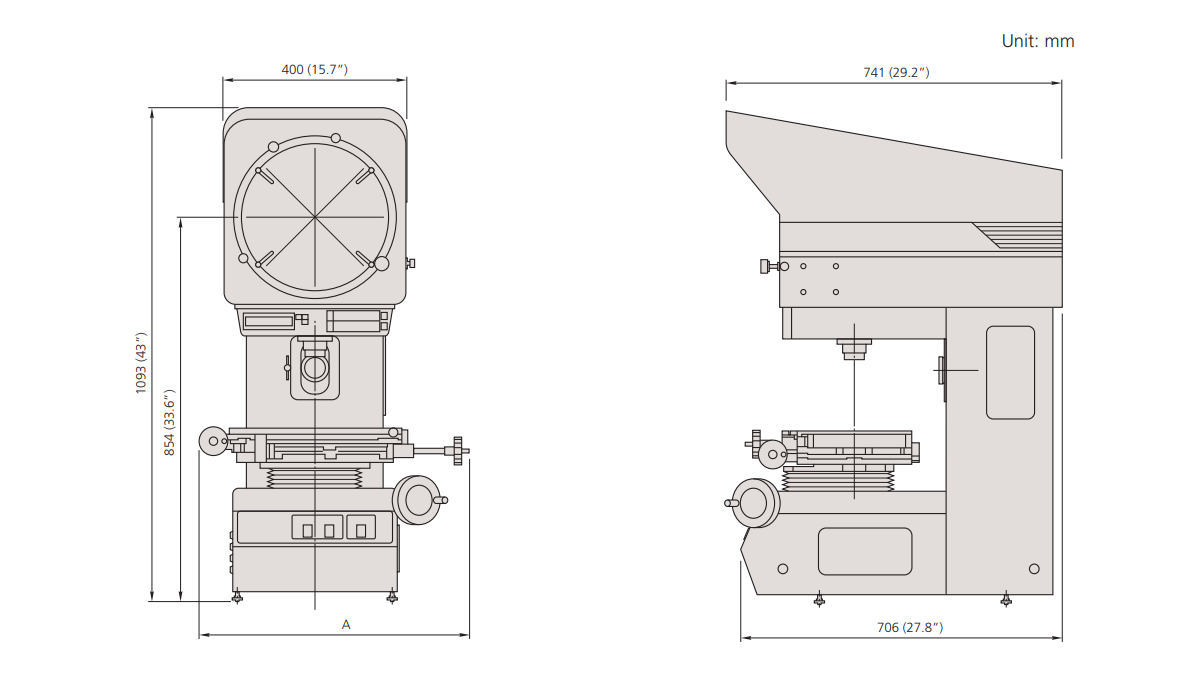 |
A | 16.8” / 427mm |
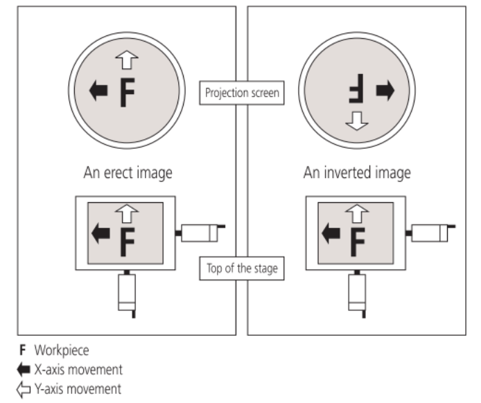
■ Erect Image and Inverted Image
An image of an object projected onto a screen is erect if it is orientated the same way as the object on the stage. If the image is reversed top to bottom, left to right and by movement with respect to the object on the stage (as shown in the figure below) it is referred to as an inverted image (also known as a reversed image, which is probably more accurate).
■ Magnification Accuracy
The magnification accuracy of a projector when using a certain lens is established by projecting an image of a reference object and comparing the size of the image of this object, as measured on the screen, with the expected size (calculated from the lens magnification, as marked) to produce a percentage magnification accuracy figure, as illustrated below. The reference object is often in the form of a small, graduated glass scale called a `stage micrometer’ or `standard scale’, and the projected image of this is measured with a larger glass scale known as a `reading scale’. (Note that magnification accuracy is not the same as measuring accuracy.)
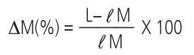
ΔM(%): Magnification accuracy expressed as a percentage
of the nominal lens magnification
L : Length of the projected image of the reference object
measured on the screen
l: Length of the reference object
M : Magnification of the projection lens
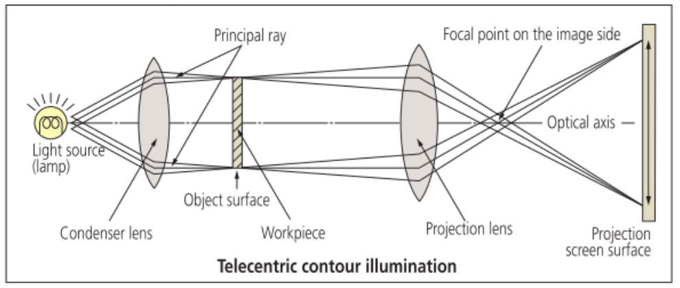
■ Telecentric Optical System
An optical system based on the principle that the principal ray is aligned parallel to the optical axis by placing a lens stop on the focal point on the image side. Its functional feature is that the image will not vary in size though the image blurs as the object is shifted along the optical axis. For measuring projectors and measuring microscopes, an identical effect is obtained by placing a lamp filament at the focal point of a condenser lens instead of a lens stop so that the object is illuminated with parallel beams. (See the figure below.)
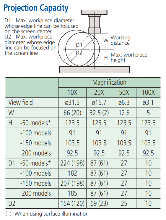
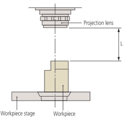
■ Working distance
Refers to the distance from the face of the projection lens to the surface of a workpiece in focus. It is represented by L in the diagram below.
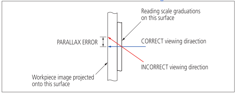
■ Parallax error
When a reading scale is used to measure the size of a workpiece feature there is always a certain distance between the reading scale, which is laid on the top of the stage glass, and the projected image of the feature which is on the underneath surface. Unless the reading scale is always viewed from the same direction, ideally from directly above, the image will appear to shift against the reading scale graduations and thus cause a measurement error.